BlogEngineering
How to design a waterproof IP65 enclosure for a PCB
Design a sealed IP65 enclosure around an existing circuit board: clearances, gasket grooves, standoffs and inserts, cable glands, venting, and 3D printing tips.
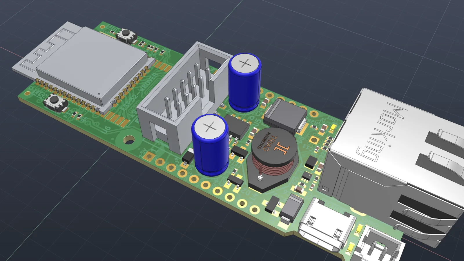
Most enclosure problems come from designing the box first and the board second. Start from the real board, its holes, its tallest parts, and its connectors, and the rest of the design follows.
1. Measure the board, not the datasheet
- Outline, thickness, and mounting holes, including their diameter.
- The tallest component on each side. Bottom-side parts and through-hole pins set the standoff height.
- Anything that overhangs the edge. Board-mounted RJ45 jacks and module antennas often stick out several millimeters.
- Connectors that must be reachable from outside, and where they face.
On an ESP32-PoE board, for example, the RJ45 jack overhangs one end by 5.6 mm and the ESP32 module’s antenna overhangs the other by 6.3 mm. A box sized to the board outline would collide with both.
2. Standoffs and inserts
Raise the board enough to clear bottom-side parts and pins, plus a millimeter or two. Heat-set brass inserts in printed standoffs hold threads far better than screws driven into plastic. Size the hole to the insert manufacturer’s recommendation.
3. The seal
- Put a groove in the case flange and a matching tongue on the lid.
- Size the gasket for 20 to 30 percent compression when the lid is down, and keep groove fill under about 85 percent.
- Space the lid screws evenly, roughly every 50 to 75 mm along the flange, so the gasket compresses all the way round.
- Keep screw holes outside the sealed perimeter, or seal them separately.
4. Getting cables in
Use cable glands sized to the cable’s outside diameter, not the thread size alone; check the gland’s clamping range. For a board-mounted Ethernet jack, a bayonet IP67 receptacle that seals around the jack keeps the box compact. Add a vent membrane so temperature swings don’t pump moist air in through the seals.
5. If you’re printing it
- PETG or ASA outdoors; ASA holds up better in sunlight.
- Four or more perimeters and high infill around the flange and glands.
- Orient the case so the sealing face prints flat and smooth.
- Test it before deploying: a hose test is cheap compared with a dead sensor.
Doing it with Vector
Give Vector the board and the requirements. It measures the outline, holes, and tallest parts, models the case, lid, gasket, inserts, glands, and vent around them, and checks every clearance. See an enclosure designed around a real ESP32-PoE board.
Questions
- What does IP65 mean?
- Under IEC 60529, the 6 means dust-tight and the 5 means protected against water jets from a 6.3 mm nozzle. It’s a common target for outdoor sensor nodes.
- Can a 3D printed enclosure be IP65?
- Yes, with care. FDM walls can wick water along layer lines, so print the sealing areas with extra perimeters, use a material like PETG or ASA, and test the finished box.
- How much should the gasket compress?
- For a solid elastomer gasket, about 20 to 30 percent of its height is a common starting point. Size the groove so the gasket doesn’t fill more than about 85 percent of it.
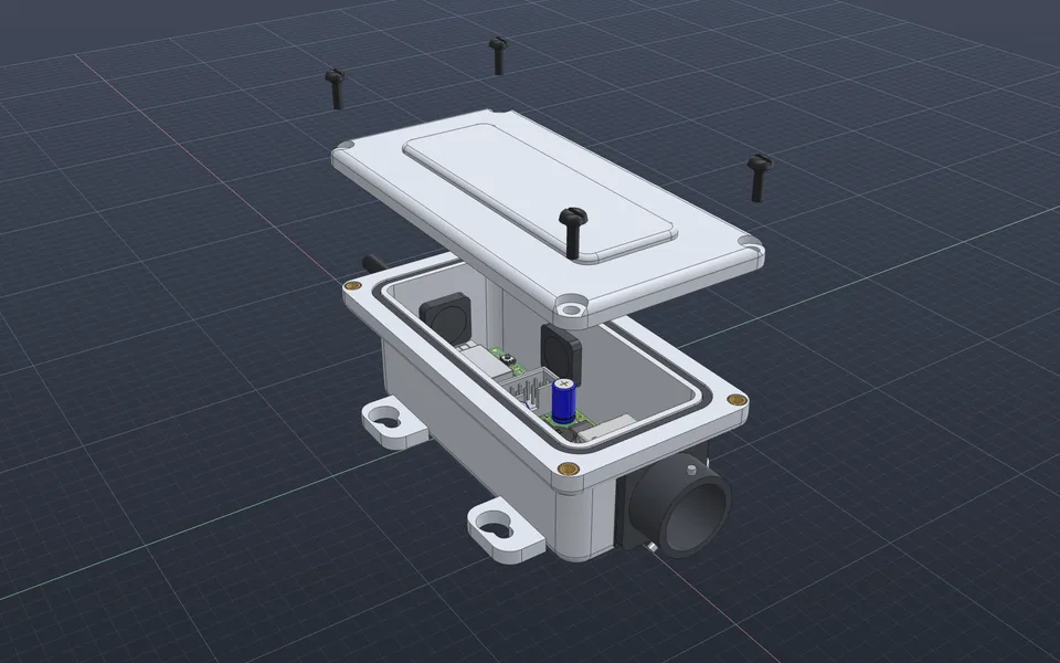
Design a sealed enclosure around a circuit board
Vector measures the board’s outline, mounting holes, and tallest parts, then models a gasketed case with inserts, sealed connectors, and cable glands, and checks every clearance before you print.
Watch it in Vector