BlogEngineering
Spur gear design basics: module, center distance, backlash, and ratio
The spur gear numbers that matter in CAD: module and pitch diameter, center distance, backlash, minimum tooth count, ratio, and a first strength check.
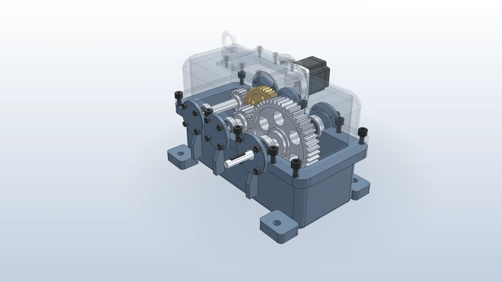
Getting gears right in CAD comes down to a handful of numbers. Get them right and the gears mesh, run quietly, and give the ratio you expect. Get one wrong and the teeth overlap in the model or bind in the hardware.
Module and pitch diameter
d = m × z
addendum = m,  dedendum = 1.25 m
outside diameter = m × (z + 2)
For an 18-tooth pinion at module 2, the pitch diameter is 36 mm and the outside diameter is 40 mm. Meshing gears share a module and a pressure angle, usually 20°.
Center distance
a = m × (z1 + z2) / 2
An 18:42 pair at module 2 sits on 60 mm centers. Build the shafts and bores to that number first, then add backlash.
Backlash
Gears need a small gap between teeth for lubrication, thermal growth, and manufacturing error. In CAD the cleanest way to add it is a slightly larger center distance: 60.15 mm instead of 60 for the pair above. Then check the gap on the model rather than trusting the number.
Tooth count and ratio
- With a 20° pressure angle, pinions below about 17 teeth start to undercut unless you use profile shift.
- Ratio is z2 / z1. Two stages multiply: 42/18 × 48/16 = 7.00:1.
- Tooth counts with no common factor spread wear evenly across teeth. 18:42 shares a factor of 6, which is acceptable for most light-duty drives.
A first strength check
Ft = 2T / d
σ = Kv × Ft / (b × m × Y)
The Lewis equation gives a quick bending stress from the tangential force Ft, face width b, module m, form factor Y, and a velocity factor Kv. It’s a first pass; AGMA and ISO 6336 methods add contact stress and more factors. See a gearbox checked against a new motor’s peak torque.
Doing it with Vector
Vector models involute gears from module and tooth count, sets the center distance with backlash, adds the gear mate, and runs a motion study to measure the ratio. See a gear stage added to a reducer.
Questions
- What is gear module?
- Module is pitch diameter divided by tooth count, in millimeters. Two gears must have the same module and pressure angle to mesh.
- How do I add backlash in CAD?
- The simplest way is to increase the center distance slightly, for example 0.05 to 0.15 mm for small module gears, or to thin the teeth. Then check the gap on the model.
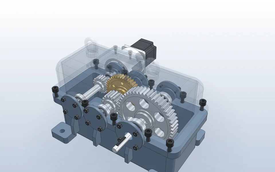
Add a gear stage and check the ratio
Vector models the involute gear from module and tooth count, sets the center distance, adds the gear mate, and runs a motion study through both stages.
Watch it in Vector