BlogGuides
How to make an engineering drawing in Fusion 360, step by step
Create a dimensioned shop drawing in Autodesk Fusion: sheet setup, base and projected views, dimensions, hole callouts, notes, title block, and PDF export.
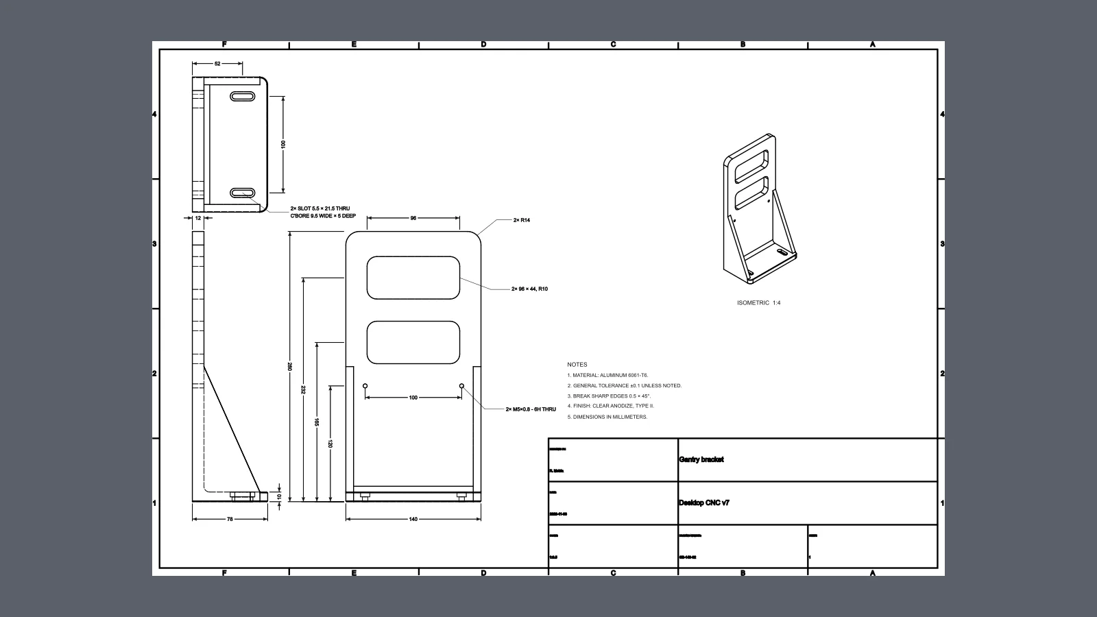
A good drawing lets a machinist make the part without calling you. Autodesk Fusion has everything you need to produce one. This walks through a single-sheet drawing for a machined bracket, from an empty sheet to a PDF.
1. Create the drawing
With the design open, choose File → New Drawing → From Design. Pick the component, the standard (ASME or ISO), units, and sheet size. A3 or B size suits most small parts.
2. Place the views
- Place the base view. Choose the orientation that shows the part’s profile, usually the one with the most features in true shape.
- Set the scale so the views fill the sheet with room for dimensions. 1:2 and 1:5 are common.
- Use Projected View to add the top and side views. Show hidden lines on the orthographic views when they clarify internal features.
- Add an isometric at a smaller scale. It helps the shop understand the part at a glance.
3. Dimension it
Dimension from the faces the shop will set up on. For a bracket that sits on its foot, measure heights from the foot: hole height, window heights, overall height. Put each dimension in the view where the feature is clearest, and don’t dimension anything twice.
4. Call out holes and features
Use hole and thread notes for tapped holes, for example 2× M5×0.8 - 6H THRU. Call out slots with their width and center distance, counterbores with width and depth, and repeated radii once with a count.
5. Notes and title block
- Material and condition, such as 6061-T6.
- General tolerance, for example ±0.1 mm unless noted.
- Edge break, finish, and anything else the shop needs.
- Part number, revision, scale, projection, and who drew it, in the title block.
6. Export
Export a PDF from the Export panel and check it at 100% zoom before sending.
Doing it with Vector
Ask for the drawing in one request: sheet size, projection, views, what to dimension, and the PDF. Vector places the views, dimensions each feature once, adds the callouts and notes, fills in the title block, and exports the file. See a drawing made from the model.
Questions
- First-angle or third-angle?
- Third-angle is standard in the US and common with ASME; first-angle is common in Europe with ISO. Pick the one your shop expects and say so in the title block.
- How many dimensions should a drawing have?
- Enough to make the part without measuring the drawing, and no feature dimensioned twice. Dimension from the faces the machinist will use as datums.
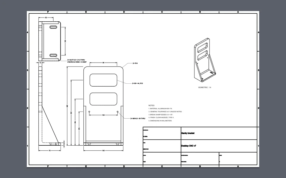
Make a shop drawing from the model
Vector places the views on a standard sheet, dimensions every feature once, calls out holes and slots, fills in the title block, and exports a PDF.
Watch it in Vector