BlogEngineering
From hand sketch to parametric part: a practical workflow
Turn a dimensioned hand sketch or photo into a fully constrained, parametric CAD part: calibrating the image, sketching with intent, and naming parameters.
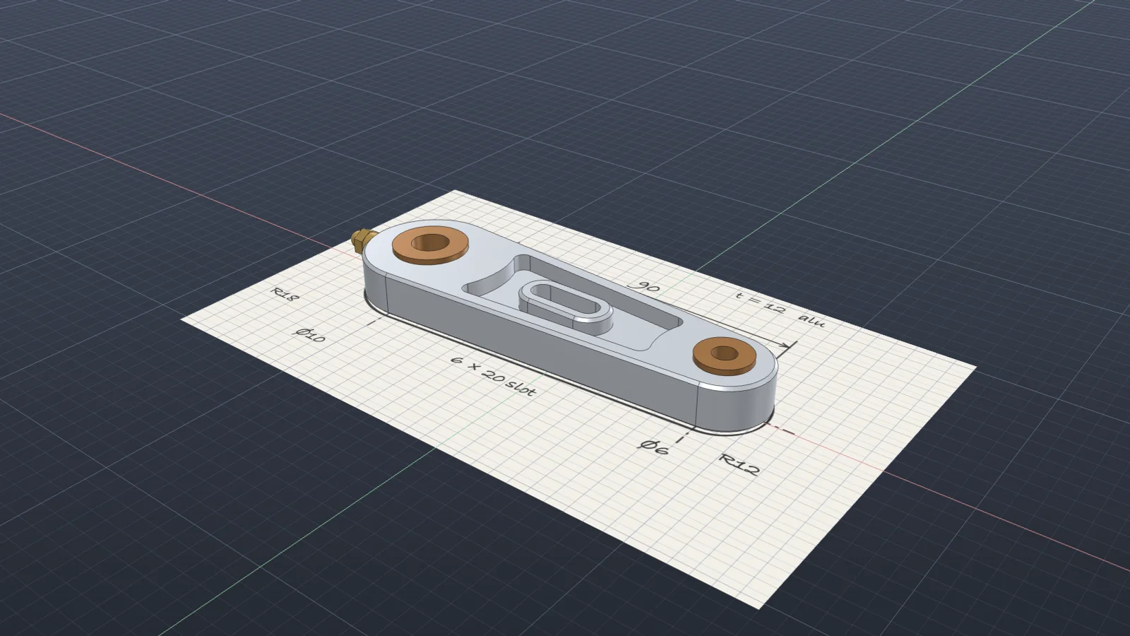
Plenty of real parts start as a sketch on paper with a few dimensions. Turning that into CAD is quick if you treat the sketch as a reference for intent, not as a tracing template.
1. Insert and calibrate the image
Insert the photo as a canvas on the right plane and calibrate it from the longest dimension on the sketch, such as 90 mm between holes. Longer reference distances give a more accurate scale.
2. Sketch from the callouts
Draw the profile from the written dimensions, not the pencil lines. The drawing says R18 and R12 ends on 90 mm centers; the pencil line might wander by a millimeter. Use the canvas to check shape and proportion.
3. Constrain it fully
Add tangent, concentric, and symmetric constraints, then the driving dimensions. When every line turns black in Fusion, nothing can drift when a value changes. See how to fully constrain a sketch.
4. Name the parameters you’ll change
If the hole spacing is going to change, make it a user parameter called hole_spacing and drive the sketch from it. Change it later and the part rebuilds.
5. Add the details and check the mass
Pockets, chamfers, bushings, and fittings come after the profile works. Assign a material and check the mass against what you expect; a pivot arm in 6061 that weighs twice what you thought usually means a missing pocket.
Doing it with Vector
Attach the photo and describe the part. Vector inserts it as a canvas, calibrates it, traces a fully constrained profile from the callouts, and makes the spacing a parameter. See a pivot arm modeled from a hand sketch.
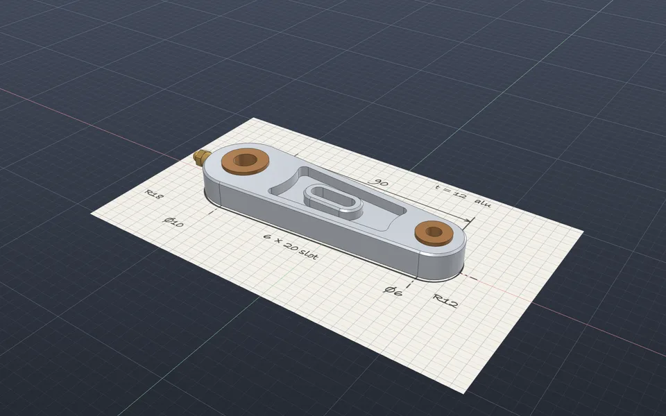
Model a part from a hand sketch
Vector inserts the photo as a canvas, scales it from a known dimension, and builds a fully constrained part with the hole spacing as a user parameter.
Watch it in Vector