BlogEngineering
USB-C power for your board: the 5.1 kΩ CC resistors and why they matter
A USB-C charger won’t turn on 5 V until it sees 5.1 kΩ pull-downs on CC1 and CC2. How to wire a power-only USB-C sink in KiCad, and the mistakes to avoid.
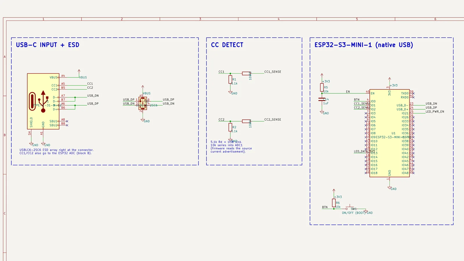
A board with a USB-C connector that powers up from a laptop’s USB-A port and stays dead on a USB-C charger almost always has the same problem: it’s missing the resistors on the CC pins. A USB-C source keeps VBUS off until it detects a device, and the device announces itself with a 5.1 kΩ pull-down on each CC pin.
How detection works
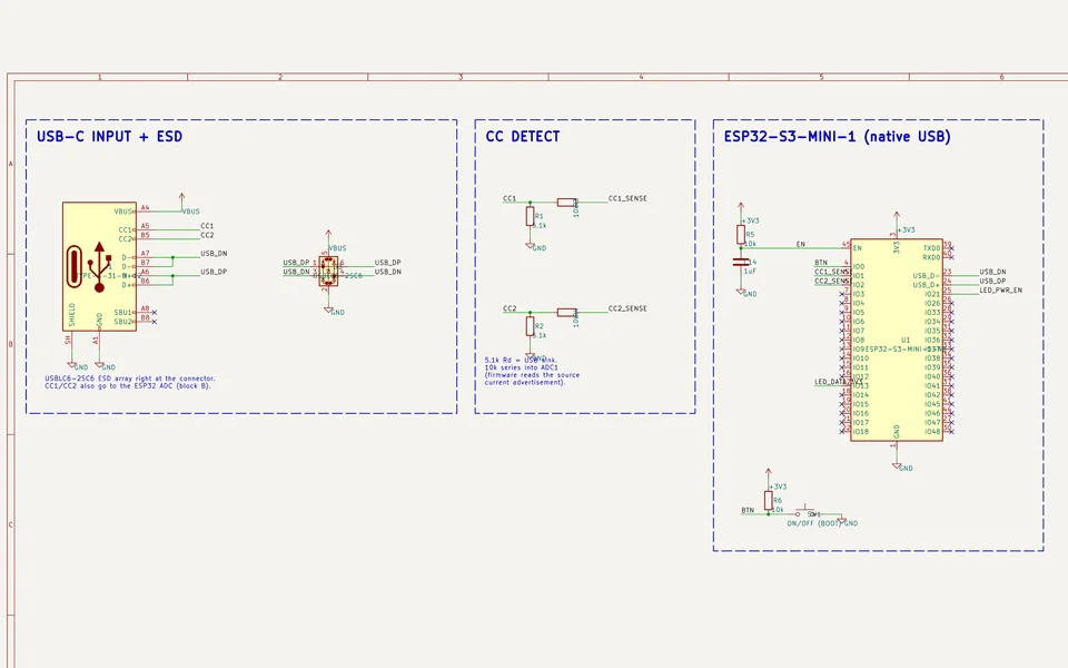
The source puts a pull-up, Rp, on its CC line. The sink puts a pull-down, Rd, of 5.1 kΩ on CC1 and CC2. The cable connects one of the two, depending on which way it’s plugged in. When the source sees the voltage divider, it turns on 5 V. The voltage the sink sees on CC also tells it how much current the source offers:
| Source advertises | Voltage on CC at the sink |
|---|---|
| Default USB power | 0.25 to 0.61 V |
| 1.5 A at 5 V | 0.70 to 1.16 V |
| 3.0 A at 5 V | 1.31 to 2.04 V |
Wiring a power-only sink
- A separate 5.1 kΩ resistor from each CC pin to ground. Don’t share one resistor between them.
- Every VBUS pin and every GND pin on the connector connected, since they share the current.
- The shell to ground, directly or through a resistor and capacitor if you want to keep chassis and signal ground apart.
- A fuse or current limit after VBUS, and an ESD array on D+ and D− if the board uses USB data.
- Optionally, CC1 and CC2 into ADC pins through a resistor, so firmware can read the advertised current.
Choosing the connector footprint
Power-only receptacles with six pins, such as the GCT USB4125, carry VBUS, GND, CC1, and CC2 and are easy to route on two layers. Sixteen-pin receptacles, such as the HRO TYPE-C-31-M-12, add USB 2.0 data. Check the footprint against the datasheet’s land pattern, and keep the connector’s mouth at the board edge with any overhang allowed for in the enclosure and the panel.
If a board works with a USB-A to C cable but not a C to C cable, measure CC1 and CC2 to ground. You should see about 5.1 kΩ on each.
Vector draws this block into KiCad schematics with real symbols and footprints and checks it with ERC. See it in a full schematic.
Questions
- Can I use one resistor for both CC pins?
- No. Each CC pin needs its own 5.1 kΩ to ground. Tying them together can confuse the source and breaks some cables.
- Why does my board work with one cable and not another?
- USB-A to USB-C cables have a pull-up built in, so power is always on. USB-C to USB-C cables leave the decision to the charger, which needs to see 5.1 kΩ on CC.
- Do I need a PD controller for more than 5 V?
- Yes. The CC resistors only get you 5 V. Higher voltages need USB Power Delivery negotiation.
Draw a schematic from a written brief
Vector picks parts JLCPCB stocks, draws each block with library symbols and footprints, and runs ERC and a netlist check before anything goes to layout.
Watch it in Vector