BlogGuides
How to make configurations with a design table in SOLIDWORKS
Use a SOLIDWORKS design table to drive a family of part sizes from Excel: naming dimensions, adding equations, suppressing features, and exporting every size.
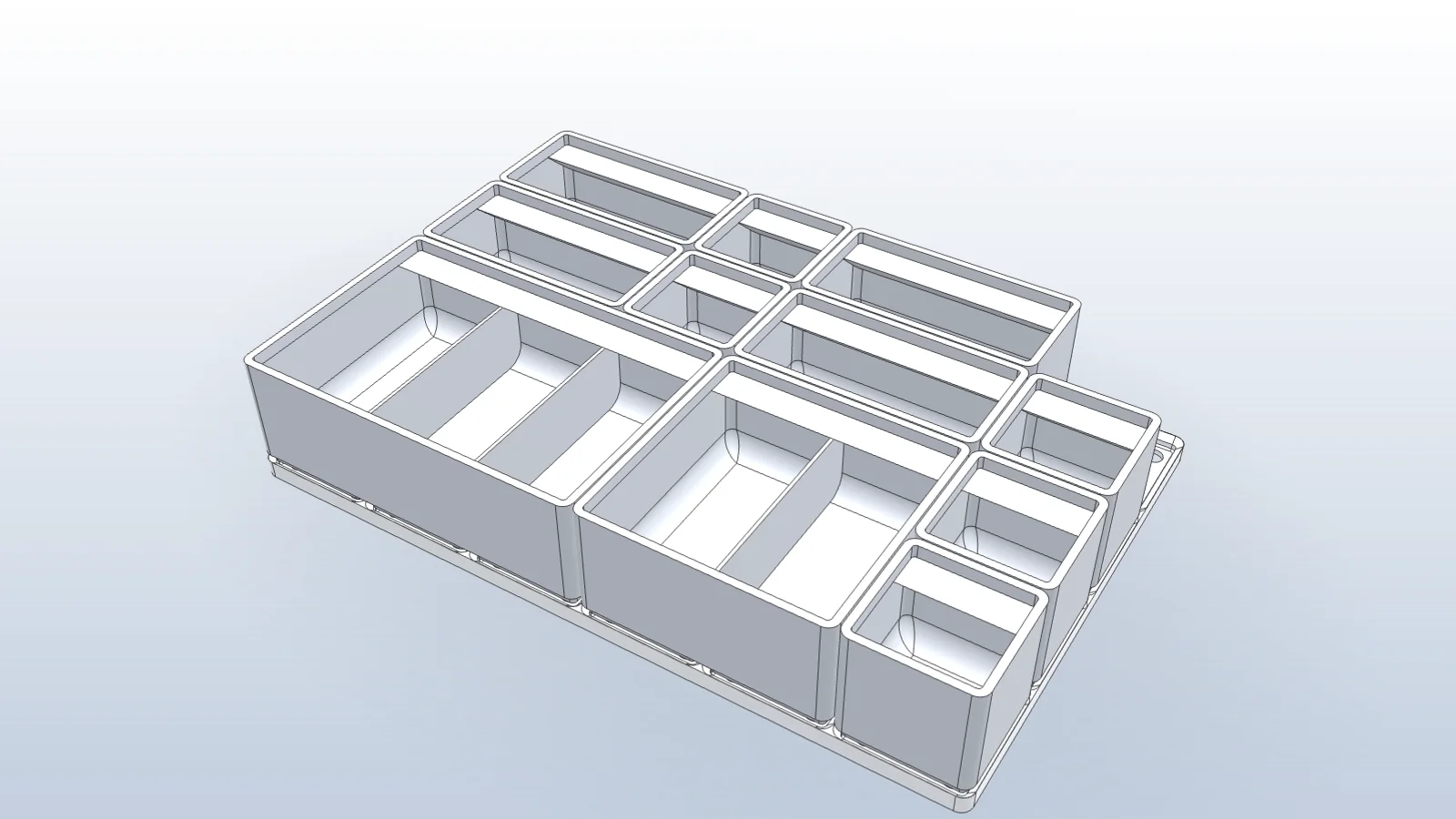
A design table drives SOLIDWORKS configurations from an Excel sheet: one row per size, one column per dimension or feature state. Set up well, it turns one part into a family you can extend in a minute. Set up badly, it breaks on the next edit.
1. Prepare the part
- Fully define the sketches, so changing a value can’t move anything unexpectedly.
- Rename the dimensions that will change.
units_x@Basesurvives edits better thanD1@Sketch1. - Put relationships into equations. For a bin on a 42 mm grid:
length = 42 * units_x - 0.5. - Make sure patterned features follow the driving dimension, so pads and dividers update with the size.
2. Insert the design table
Use Insert → Tables → Excel Design Table and choose Auto-create to pick the dimensions. Each row becomes a configuration. Columns can drive dimensions, suppress features with $STATE@FeatureName, and set properties like $PARTNUMBER.
| Configuration | units_x@Base | units_y@Base | $STATE@Divider |
|---|---|---|---|
| 1x1 | 1 | 1 | S |
| 2x1 | 2 | 1 | U |
| 2x2 | 2 | 2 | U |
| 3x2 | 3 | 2 | U |
3. Check every size
Activate each configuration and rebuild. A size that fails usually exposes an equation or a pattern that doesn’t scale. Fix it in the base part, not in one configuration.
4. Use and export the family
Insert the part into an assembly and choose the configuration per instance. To export each size, activate it and save as STEP or STL, or script it. See a bin family built from a design table and exported.
Questions
- Design table or equations?
- Both. Equations express relationships inside one size, like length equals units times pitch. The design table picks values for each size.
- Why does my design table break after an edit?
- Usually a dimension was renamed or a feature deleted. Use named dimensions instead of defaults like D1@Sketch1, and keep feature names stable.
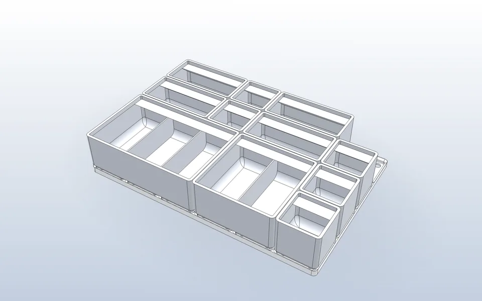
Make a part family with a design table
Vector drives the changing dimensions from equations, builds each size as a configuration, places them in an assembly, and exports a file for each size.
Watch it in Vector